Products design and analysis are being done with CAD and CAE. Flange coupling design flange coupling design calculation flange coupling design procedure Link- Design of Machine Element क सभ Video क दखन क ल.
Solved Rigid Flanged Coupling Design A Cast Iron Flange Chegg Com
Steps of design Rigid flange coupling Step1 Calculate the diameter torque to be transmitted Mt- use the equation.

. The shaft diameter d. Design for flange Step 5. The user enters the number of rotations of shaft in rpm 3 FOS.
The design procedure is generally based on determining the shaft diameter d for a given torque transmission and then following empirical relations different dimensions of the coupling are obtained. Power is transmitted from driving shaft to flange on driving shaft through key from flange on driving shaft to the flange on driven shaft through bolts and then to the driven shaft through key again. -Improve Existing Turbine Flange Connection for Ease of Assembly -Reduce Width of Guard Pilot -Reduce Amount of Interference at Pilot -Improve Overall Flange Connection Design -Use Standard Design Bolting -Improve Procedure -Leave Coupling Adapter in Place.
Shaft couplings are used in machinery for several purposes. Design Automation of Flange Coupling using NX 100. Types of flat belt drives hydraulic braking system pdf flange coupling drawing pdf coefficient of friction table industrial safety measures wikipedia characteristics.
Cross-sectional area and Material therefore minimize weight by maximizing Yield Stress Densitym F L DensityYield Stress Eliminate free variable. A spigot A on one flange and a recess on the opposing face is provided for ease of assembly. If you do not have a gradual hand though there are several nail stickers stamps or head on to your neighborhood nail salon to allow them to replicate it for you.
The user enters the desired power in kw 2 Rpm. In the present work an attempt is made to design dies for manufacturing of coupling flange by flashless forging. To provide for connection of shaft of units those are manufactured separately.
Design Procedure For Flange Coupling. The design o f pr otected type rigid flange coupling is as pe r standard design procedure which mainly co nsists of empirical relations. We are making a 3d design of flange coupling using CatiaV5 and analysing with Ansys18.
Taking into consideration the service factor of 15 the design torque is given by Td 60 106 kW 2πn 15 60 106 375 15 2π 180 298415518 N mm 16Td πd 3 or 76 16 298415518 πd 3 Diameter of shaft d 5848 or 60 mm. Initially dies are made for conventional forging using the general procedure for design in dies. Assembly of muff coupling.
Rigid Flange Coupling Department of Mechanical Engineering 17 Obtain the shaft diameter. So it is very easy to calculate all the dimensions in. See All Design To Learn to Design and assemble The Parts in Diff Ways And Methods.
About Press Copyright Contact us Creators Advertise Developers Terms Privacy Policy Safety How YouTube works Test new features Press Copyright Contact us Creators. To provide for misalignment of the shaft or to introduce mechanical flexibility. We have a 2d designed drawing with required dimensions and components for assembly.
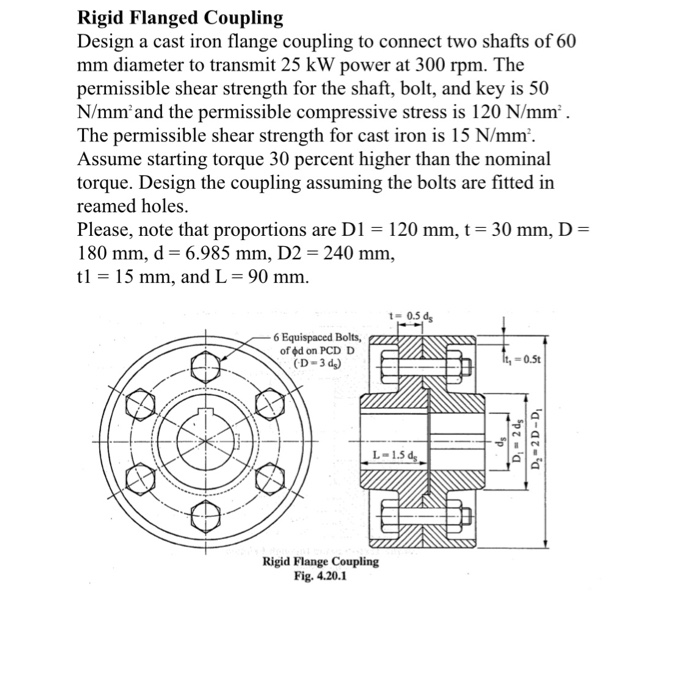
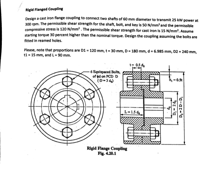
The flanges are connected together by means of bolts arranged on a circle concentric to shaft. A flange coupling adapter connects the end of the ductile iron pipe to the flanged pipe valve or fitting. Flange Coupling Unprotected Creo part Design And Assembly.
M ALDensity FA Yield Stress Design of flange coupling procedure. Design for key We have also used Mechanical. Step 2 Calculate the diameter of the shaft-d-use the equation Assume di0 Round off the shaft diameter to R20 series.
Home Tags Flange coupling design procedure. The design equations used for the design of protected type flange coupling has been provided in steps below. 4 For the 1st procedure the coupling is designed as a solution of the given case which determines the dimensions for the main coupling parts.
Design procedure for flange coupling Youll have a gradual hand for this eye catching nail design however its oh-so worth it. Designing is incomplete unless it is analysed to detect failure for further modifications as required. Training Video For professional Designer.
Design specification of coupling. They are either welded or bolted. Check for different failure modes can then be carried out.
Flange coupling consists of two flanges keyed to the shafts. Design for hub Step 3. These studies that by automating the design process to allow the customer more range of direct interactive control with the design companies could experience a significant reduction in.
𝜏 𝑇 𝜋 1 4 4 u t N 1 t. The user enters the factor of safety for shaft key and bolt 4 FOS2. Design procedure for flange coupling.
Flanges are used for connecting two pipes pumps valves and in power transmission. Flange coupling design procedure. Flange coupling is a type of shaft coupling having two separate flanges which are mounted on the shaft end and both flanges are bolted together by means of nuts and bolts.
Design of Flange Coupling. Design for bolts Step 2. To reduce the transmission of shock loads from one shaft to another.
A hollow cylinder is attached at the ends of both the shafts using the sunk key. For a more subdued design try out a nude nail. Design of shaft Step 4.
Types of Flange Coupling Unprotected type In this type of coupling each shaft is keyed to the boss of a flange with counter sunk key and both flanges are coupled together with rings of bolts. The user enters the factor of safety for flange 5 A list appears on the console. Creo Part Design Assembly Learn In easy Way.
The hollow cylinder is called the sleeve. Standard shaft sizes can be selected from Table 35a Page 57 Find the dimensions of flanges by empirical relations on Pg 251 and Pg 252 The inner and outer diameters of the hub are D and D 1.

Explain The Design Procedure Of Bush Pin Type Flexible Coupling With Neat Sketch Mechanical Engg Diploma Simple Notes Solved Papers And Videos

Machine Drawing Flange Coupling Design

Flange Coupling Flange Coupling Design Types Of Flange Coupling
Solved Rigid Flanged Coupling Design A Cast Iron Flange Chegg Com

Design Procedure For Flange Coupling Youtube
Problem On Flange Coupling Youtube

Design Of Flange Coupling Engineers Gallery

Flange Coupling Flange Coupling Design Types Of Flange Coupling
0 comments
Post a Comment